Motor Protection Relay Setting: How to Determine the Current Value on a Vacuum Pump
Table of Contents
- What the Protection Relay Protects
- The Difference Between Nameplate Current and Actual Current
- Steps to Determine the Setting Value
- Starting Current and Time Delay
- Consequences of an Incorrect Setting
- Verifying and Recording the Setting
A motor protection relay exists to protect the motor from overcurrent and the winding damage that follows. However, if the relay is set too low the pump stops unnecessarily; if it is set too high, it trips only after the motor has already been damaged. This article explains how to determine the relay setting for a vacuum pump and what needs attention.
What the Protection Relay Protects
The relay continuously monitors the motor current. If the current stays above the permitted value for a defined time, it opens the contactor and takes the motor out of service. This protection prevents the windings from overheating and their insulation from breaking down.
The relay's role is not to prevent a fault but to stop a fault from growing. The more accurately the setting is made, the more effective the protection will be.
A motor protection relay continuously monitors the current flowing through the motor windings and opens the circuit when the current stays above the set value for a long time. In a vacuum pump the task of this device is to prevent insulation damage caused by motor overload. Unlike a fuse, the relay tolerates short and harmless increases in load and trips only when a real danger has arisen.
Running a pump without a protection relay greatly shortens the life of the motor. A winding that runs under excess current first heats up, then its insulation weakens and finally it fails with a short circuit. A correctly set relay provides a chance to stop this chain at its beginning, and protects both the motor and the pump.
The relay is usually connected so that it measures the current of all three phases on a three-phase motor. When a phase is lost or phases are unbalanced, the relay detects the unbalanced current and takes the motor out of service. This feature plays an important role in preventing serious faults such as running on a single phase. The working of this function should be tested periodically.
The Difference Between Nameplate Current and Actual Current
The rated current printed on the motor nameplate is the value drawn when the motor runs at full load. The actual operating current of the pump, however, can vary with the vacuum level, the service liquid quantity and the conditions of the process. The pump may not always run at full load.
For this reason, looking at the nameplate value alone is not sufficient when setting the relay. The current measured under normal operating conditions of the pump must also be taken into account.
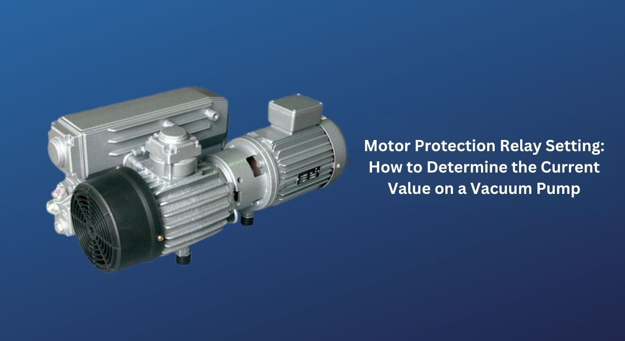
Thermal type relays work on the principle that current is converted into heat and a bimetal strip bends. This type responds in a way similar to the real heating of the motor, and it acts not on sudden loads but on long lasting overloads. Electronic relays offer finer adjustment and a shorter response time, but they need correct configuration.
The basic function of the protection relay is to prevent the motor from exceeding its permitted temperature limit. This limit is linked to the insulation class and the values set by the motor manufacturer. The relay should be set with a time characteristic that suits this class. A setting that does not match the motor class leads either to unnecessary trips or to damage to the motor.
When setting the relay, it is necessary to know how much current the motor actually draws under the real operating conditions of the pump. This information can differ from the value on the motor nameplate and should be measured with the real load on site. A correct measurement ensures that the relay does not trip unnecessarily in normal running and reacts quickly to a real overload.

Steps to Determine the Setting Value
First, note the rated current on the motor nameplate. Then run the pump under normal operating conditions for a while and measure the current of each phase with a clamp meter. The three phase values should be close to one another; a large difference may point to a fault in the connection or the motor winding.
Record the highest normal current value measured. The relay setting is usually made so that it falls within the ratio range set by the manufacturer. The relay should not be set so low or so high that it falls outside this range.
The connection of the protection relay should be considered together with the current transformer and the contactor. If the relay is connected to the wrong point, or if it is not properly coordinated with the contactor, the protective function does not work as expected. The panel diagram should clearly show the connection points and cable cross-sections, and its revisions should be recorded.
The nominal current of the motor is on the motor nameplate and is the basic reference for the relay setting. However this value alone is not sufficient; the load at which the pump runs, the temperature conditions and the line resistance must also be taken into account. The setting should not be fixed at a point just below or above the nameplate value, but determined according to the real load.
The motor nameplate usually shows both the nominal current and the service factor. The service factor indicates that the motor can run briefly above its nominal value. Taking the service factor into account when setting the relay reduces unnecessary trips. However the service factor is not permission for a continuous overload, and this distinction must be well understood.
Starting Current and Time Delay
At the moment the motor starts, it draws a starting current several times its rated value. The relay should not trip during this brief surge. The time delay of the relay must therefore be long enough for the start and set so that it avoids nuisance tripping during start-up.
If the time delay is set too long, the motor can be damaged for a long time in a real overload. If it is set too short, the pump will stop unnecessarily even during a normal start.
All the values for setting the motor protection relay should be written down on paper. The nameplate values, the relay type, the current transformer ratio and the nominal value of the contactor should appear together in a table. This table is used as a reference for any future change and explains why the setting was made in that way.
The most common result of wrong relay setting is the motor tripping frequently and production stopping. In this situation operators often tend to raise the setting, and this exposes the motor to a real danger. The correct solution is to find the cause and measure the real load. Raising the setting at random removes the purpose of the protection system.
A setting that is chosen too low causes trips even during normal running of the pump. Short current peaks that occur at the moment of starting are wrongly detected by a relay with a low setting, and the motor keeps switching off and on. This causes unnecessary wear on the motor and on the contactor and reduces the reliability of the pump.
Consequences of an Incorrect Setting
If the relay is set too low, the pump trips frequently. Operators experience this as the pump "stopping by itself", and they often mistakenly blame cooling or control faults. This disrupts production and shortens the life of the contactor.
If the relay is set too high, the motor runs in overload for a long time. The winding heats up, the insulation weakens and eventually the motor can burn out. In this case the relay becomes a late warning rather than a way to prevent the fault.
Another result of a wrong setting is that a real fault is noticed late. If the relay does not trip when a phase is lost or when there is a high imbalance, nobody may notice until the motor is damaged. For this reason periodic verification of the setting is important to show that the protection system really works.
The results of a setting are not limited to the motor alone. A relay that trips often also affects the process line to which the pump is connected. A fall in vacuum can cause quality problems in the process and loss of product. This chain shows why the cost of a wrong setting is not just an electrical matter.
Signs of a wrong setting appear as repeated trips, a motor that is always hot, and noise or heating at the contactor. When these signs appear, the setting value should be reviewed together with a measurement of the real current. Recording the signs helps to understand what changed and when, and supports the right decision.
Verifying and Recording the Setting
After the setting is made, verify the tripping behaviour by running the relay in test mode or with a controlled load. Record the relay setting together with the measured current values and the date. The setting should be checked again whenever the motor or the coupling is changed.
It is essential that electrical settings are made only by authorised and trained personnel. When working inside the panel, isolate and lock out the supply and confirm that it is de-energised.
Verification of the setting should be carried out after commissioning and at set intervals. During verification the test button on the relay can be used, and its response to a real overload can be measured. The result of each verification should be recorded together with the date and the name of the responsible person.
The record forms the setting history of the relay and lets the next person understand what was changed and why. The setting value, the real current value, the relay type and the protection chain it belongs to should all be written together. Without this record, following a setting that was made is almost impossible and information is lost between teams.
In conclusion, correct setting of a motor protection relay is not a one-off job. Ageing of the motor, changes in load, an increase in line resistance and changes in ambient temperature can all require the setting to be reviewed again. Regular verification and recording keep the pump working safely for many years.